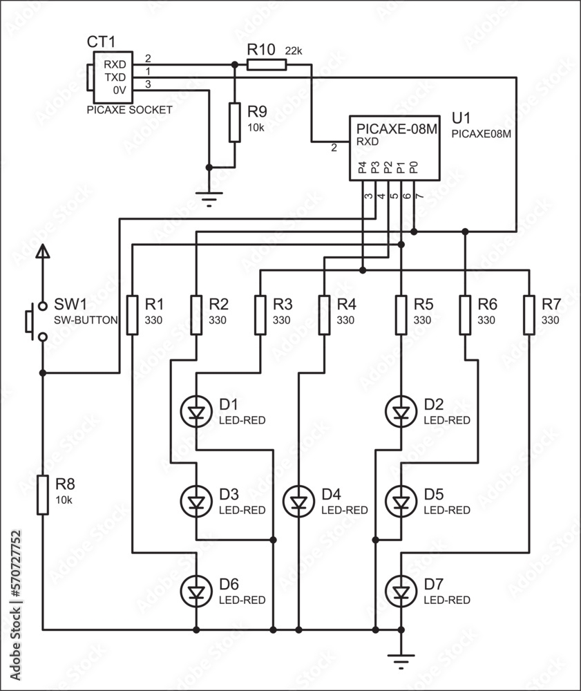
Electrical schematic drawing is a crucial aspect of electrical engineering and design. It involves creating diagrams that represent the connections and components of an electrical system in a clear and concise manner. These drawings are essential for planning, designing, and troubleshooting electrical systems in various industries.
Creating an electrical schematic drawing requires a thorough understanding of electrical symbols, codes, and standards. It helps engineers and technicians visualize the layout of the system, identify potential issues, and ensure that the system operates efficiently and safely.
When drawing an electrical schematic, it is important to use standardized symbols to represent components such as resistors, capacitors, transistors, and power sources. These symbols help convey information about the function and connections of each component in the system.
Additionally, drawing techniques such as using different line types, colors, and labels can help improve the readability and clarity of the schematic. Proper organization and layout of the drawing also play a key role in ensuring that the information is easy to understand and interpret.
Electrical schematic drawings are used in a wide range of applications, including circuit design, automation systems, power distribution, and control systems. They are essential for documenting the design and construction of electrical systems, as well as for troubleshooting and maintenance purposes.
In conclusion, electrical schematic drawing is a fundamental skill for electrical engineers and technicians. It allows them to communicate ideas, concepts, and designs effectively, and is essential for the successful implementation of electrical systems. By following standardized symbols and drawing techniques, engineers can create clear and accurate schematics that help ensure the safety and efficiency of electrical systems.
